Ethernet & VLANs
Setup
Packet Tracer can be downloaded from here. You will need to sign up for an account. You can use your institutional email.
Packet Tracer intro
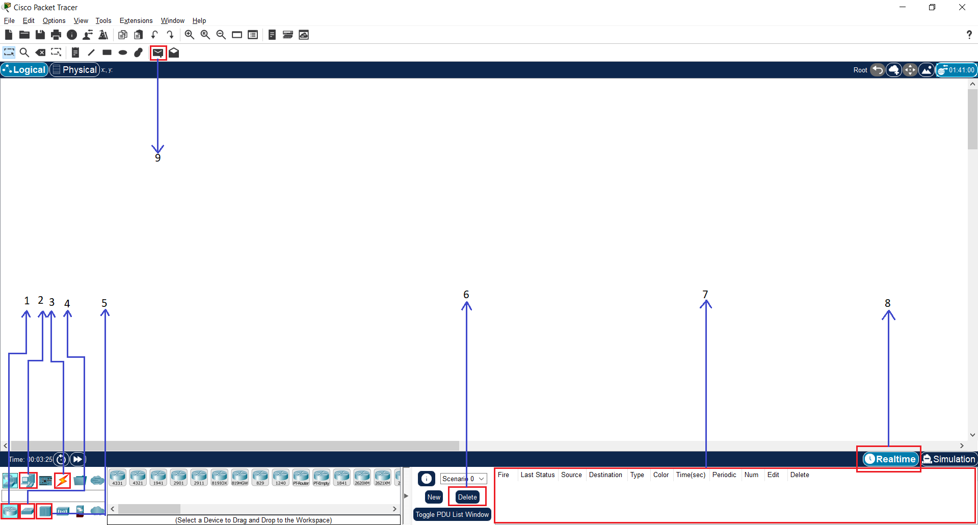
Packet Tracer is a utility with which you can simulate network topologies using hubs, routers, switches and computers. We will introduce the main components in the workspace:
- When pressed, several router models will appear to the right of it. Simply choose the Router-PT model and place it in the workspace (white middle part) wherever you want.
- When pressed, several computer models will appear to the right of it. Simply choose the PC-PT model and place it in the work area (white middle part) wherever you want.
- Choose the type of connection (UTP straight, UTP cross-over, serial connection, etc.). Simply choose the first cable type (the one labeled Automatically Choose Connection Type, with the orange lightning bolt icon), this automatically sets the connection type between two devices. After selecting the cable type click on the equipment you want to connect. In some cases you will have to choose the port of the equipment (e.g. FastEthernet 0/1, FastEthernet 0/2, etc.).
- When pressed several switch models will appear to the right of it. Simply choose the Switch-PT model and place it in the work area (white middle part) wherever you want.
- When pressed several hub models will appear to the right of it. Simply choose the Hub-PT model and place it in the working area (white middle part) wherever you want.
- You can use the Delete button to delete the history of sent packets.
- The lower right pane will display the sent packet and the status of the reception (Last Status).
- You can select the operating mode: Realtime (default mode) or Simulation (click on the tab behind Realtime to activate it). In Simulation mode you can see step by step how the packets flow between the active devices. While in Simulation mode, send a packet and then press the Auto Capture/Play button.
- You can send a packet between two Layer 3 entities (computer, router). After selecting this function, click on the devices between which you want to send packets.
- Create a topology with 2 linked switches and 2 computers linked to each of the switches.
- Before packets can be sent, IP addresses must be configured on each of the computers. When you click on a computer, a window will appear where you can configure the computers. Go to the
Desktoptab and click on theIP Configurationicon. - Fill in the IP Address field with an IP address in the range
192.168.1.1-192.168.1.5and the Subnet Mask field with the value255.255.255.0. The rest of the fields remain empty. - Check connectivity between each 2 computers using facility 9 above.
Switch vs Hub
We want to study the differences between a switch and a hub. We will simulate packet forwarding between hosts using a Packet Tracer topology in which there are 2 networks with 4 computers each. The difference between the topologies is the interconnecting device: one uses a switch and the other uses a hub.
Wait for the ports in the switch to light green (not orange) and then send packets between any 2 computers in the 2 topologies to make sure there is connectivity (lights will remain orange for about 30 seconds until STP - Spanning Tree Protocol - converges).
Once you have checked for connectivity, go into Simulation mode and send a packet between 2 computers. Do this for both networks. Observe which packets are generated on the network in each case.
What is the difference between the switch and the hub?
At what level in the OSI stack do they each run?
Populating the switching table
We want to trace how the switching table is populated. The topology consists of a switch and 4 hosts. Load the topology file into Packet Tracer and wait for the ports to light green instead of orange (wait for STP to converge).
To configure a switch, we usually use the CLI. In this lab we will mostly use the Graphical user Interface (GUI), but some functionality will need CLI access.
To access the CLI of a switch simply select a switch, then select the CLI tab in the new window. Press the Enter key on your keyboard once before writing any command.
In order to show the switching table of a Switch, we will use the following commands:
enable
show mac-address-table
Display the switching table and notice that it is empty.
The switching table
The switching table contains several columns, two of which are of interest:
- the Mac Address column specifies the MAC address
- the Ports column specifies the switch port
The table is thus an association between a MAC address and a port. We say that the tables have, for each entry:
- a match component - a MAC address is searched for
- an action component - based on the result of the match operation the packet is sent to the corresponding port.
The search part can appear once, the action part several times:
- we can have multiple MAC addresses corresponding to one port
- a MAC address can appear at most once in the switching table.
Find the name/number of each port of a switch and the MAC address of a host.
Send a packet from PC0 to PC1. Display the switching table again.
Notice the addition of two entries:
- One entry is generated when sending the PC0 packet to PC1 - it contains the MAC address of the PC0 host and the port on which it is connected to the switch
- The second one is generated when returning the packet from PC1 to PC0 - it contains the MAC address of host PC1 and the port on which it, in turn, is connected to the switch.
Send a packet from PC1 to PC2. Display the switching table again. Why only one entry, not two?
Send a packet from PC2 to PC3. Display the switching table again. What do you notice?
Clear the switching table.
You can use the clear mac-address-table command form the CLI to clear the switching table.
Enter Simulation mode and send a packet from PC1 to PC3. What do you see? You see a summary of the sent packets in the Event list window.
Send another packet from PC1 to PC3. Why did it behave differently this time? Display the switching table again.
Clear the switching table from the CLI using the clear mac-address-table command.
Enter Simulation mode and send a packet from PC1 to PC3. At each simulation step, view the switch's switching table.
The switching table reloaded
Switching table analysis
We want to trace the contents of the switching table in a scenario with 2 switches. 2 computers are connected to each switch.
Load the topology file into Packet Tracer and wait for the switches to run STP. After STP converged, the ports of the switches will be colored green.
Send packets between any 2 computers on the network and view the switching table on both switches. Notice that a port can have multiple MAC addresses associated with it.
The port of one switch that links to the other switch contains three MAC addresses:
- the MAC address of the port of the other switch
- the MAC addresses of the hosts connected to the other switch
Removing equipment
Display the switching table of Switch0 and note the port associated with the MAC address of host PC1.
Disconnect the PC1 host from the network by pressing the green light on its link to Switch0 followed by the Escape key (another way to delete a link can be achieved by using the "X" button on the right, followed by pressing the item to be deleted).
After unplugging the computer, watch the switching table and note the loss of the related entry.
Reconnecting equipment
Use a Copper Straight-Through cable to connect the PC1 host to the other available port of the Switch0 switch (different from the initial one).
After STP converges on the switch, send a packet between PC1 and PC0.
Note the populating of the switching table with a new entry corresponding to the MAC address of host PC1. A MAC address cannot appear twice in a switch's switching table.
VLANs intro
Virtual Local Area Networks (VLANs) are ways of logically separating a local area network (LAN) into multiple subnets on the same physical infrastructure.
Separation is accomplished at the Data Link level by inserting an additional field in the level 2 header. VLANs are identified within the frame by a VLAN ID.
Configuration of VLANs is performed on the switches, specifically on the switch interfaces/ports.
Hosts are not aware of the existence of VLANs; their perspective is that of a local area network, i.e. the virtual network related to a VLAN ID. A host will find itself in the VLAN specific to the port to which it is connected (existing configuration on the switch).
In the topology, hosts PC0 and PC2 belong to VLAN 10, and hosts PC1 and PC3 to VLAN 20. Notice that they can only communicate two by two, although their IP addresses are in the same address space.
The configuration of the two VLANs was performed on the Switch0 switch.
In order to check the VLAN configuration on Switch0, click on it, select the Config tab in the new window then VLAN Database in the side panel.
Also, for each interface, you will see a line for VLAN configuration, specifically the type of port (access or trunk) and the allowed VLANs.
Access ports
In the topology there is a network with a switch, a management host and 4 other hosts (PC1, PC2, PC3, PC4) for users. Notice that the hosts can communicate with each other.
We want to isolate PC1 and PC3 from the other hosts (PC2 and PC4) so that PC1 can only communicate with PC3.
This can be accomplished by configuring the ports associated with PC1 and PC3 to be part of VLAN 10 and the ports associated with PC2 and PC4 to be part of VLAN 20.
After creating the VLANs in the switch database, configure the ports to be part of these VLANs as follows:
- Fa1/1 -
PC1- VLAN 10 - Fa2/1 -
PC2- VLAN 20 - Fa6/1 -
PC3- VLAN 10 - Fa3/1 -
PC4- VLAN 20
Check the connectivity between each pair of hosts. Note that hosts in the same VLAN can communicate with each other.
Trunk ports
On the given topology from exercise 03, make a fiber optic link between the switches Switch0 and Switch1 on the Fa4/1 port of each switch.
Test connectivity between hosts in the same VLAN but different switches. Notice that there is no connectivity because there is no mechanism enabled for VLANs on different switches to communicate with each other.
To enable connectivity between hosts that are in the same VLAN but connected through different switches, we need to configure the link between the switches in trunk mode.
This link allows the encapsulation of packets with different VLANs.
Identify the interconnect port number on each of the switches. On each switch, enter the appropriate interface and set the link to trunk mode.
On Switch0, configure the Fa4/1 interface in trunk mode and allow access to all VLANs.
On Switch1 configure the Fa4/1 interface in trunk mode and allow access to all VLANs.
Investigate the trunk configuration on both switches.
Notice that the Fa4/1 interface is a trunk interface that carries VLANs 1 (the default), 10, and 20. In the case of Switch0 it also transfers the management VLAN (100).
Verify that hosts in the same VLAN can communicate with each other regardless of which switch they are interconnected to.
Cascading trunk ports
We want to build virtual local area networks (VLANs) on a multi-switch topology. We will use trunk links between the switches.
The topology contains 4 hosts (PC0, PC1, PC2, PC3) and three switches (Switch0, Switch1, Switch2).
The four hosts already have their IP addresses configured and must be two by two in VLANs:
VLAN 10: PC0 and PC2
VLAN 20: PC1 and PC3
First, after STP converges, check the connectivity between all four hosts.
With no VLAN configurations made on the switches, the hosts can communicate with each other.
Configure the switches so that the hosts can only communicate within their own VLAN (have Layer 2 separation).
Note that all VLANs (10 and 20) must be created on all switches.
Verify by forwarding packets between any two hosts.
Debugging VLANs
We plan to discuss how we troubleshoot problems in working with VLANs.
The topology contains five hosts that are in two VLANs, as follows:
- hosts
PC0,PC1andPC3are in VLAN 10 - hosts
PC2,PC4are in VLAN 20
Check why there is no connectivity between hosts PC0 and PC1, even though they are connected to the same switch. Investigate Switch0.
Check why there is no connectivity between hosts PC2 and PC4. Investigate the configuration for the trunk VLAN on Switch1.